How do 3D transforms of iOS views work under the hood?
First: the iOS coordinate system
As a refresher: the global origin point (0, 0) of the iOS world is the top-left corner of the screen (or, well, of the scene, for those multi-window iPad apps). From the top left, values are positive going to the right + downwards (Figure 1).
One property we also know about when dealing with more complex view layouts, is a view’s layer’s z-position. This effects how far ‘in’ or ‘out’ of the screen a view appears relative to its siblings, and we can use this to force sibling views to be above/below one another. For any view, it’s typically accessed as follows:
let view = UIView()
// the view's z-position relative to its siblings
view.layer.zPosition = 666

Figure 1: The x-y coordinate system for iOS.
So, if we take our regular idea of a CGPoint being (x, y) and simply tag on whatever value the zPosition happens to hold, we arrive at our idea of a three-dimensional coordinate system on iOS, with points described as (x, y, z).
CATransform3D
When it comes to transforming a view, one can think of it as applying a calculation to each individual point of the view’s layer, such that for every (x, y, z), we obtain a new (x', y', z'). That calculation is actually a multiplication of the coordinates (x, y, z) by a matrix (good ol' linear algebra). How we construct our matrix is through the use of various types of CATransform3Ds, which we’ll now dive into.
The identity matrix
The most basic three-dimensional transformation of a layer in iOS (CATransform3D) is the identity matrix. Any attempt to transform a view by the identity matrix results in no visual change to the user, as we are quite literally just multiplying by 1.
The handy shortcut for initializing this is CATransform3DIdentity, as below:
let matrix = CATransform3DIdentity
Typically, if one thought about three dimensions and then an identity matrix, one might be inclined to think that it would be a 3x3 matrix. However, as the documentation for CATransform3DIdentity will tell us, it’s actually a 4x4:
 _              _
| 1   0   0   0  |
|                |
| 0   1   0   0  |
|                |
| 0   0   1   0  |
|                |
|_0   0   0   1 _|
Why? Aren’t coordinate systems in 3D space just (x, y, z)? Well, while not needed for rotations or scales, the extra dimension is actually required for translations, the reason being that rotations and scales are multiplication operations, whereas translations are additions and subtractions. Still muddy? No worries, let’s take a look at those translations now and try to clear the air.
Translations
A translation matrix is defined as follows:
 _                 _
| 1    0    0    0  |
|                   |
| 0    1    0    0  |
|                   |
| 0    0    1    0  |
|                   |
| t    t    t    1  |
|_ x    y    z     _| // Apple's transformation matrix for a translation by tx, ty, and tz.
Here, t is our translation vector, such that tx corresponds to the translation along the x-axis, ty along the y-axis, and tz along the z-axis. We create this matrix by calling CATransform3DMakeTranslation if we need the reference to the translation matrix itself, or CATransform3DTranslate if we wish to apply the transformation right away.
Again, we can ask the question, “Why do we need a 4th set of values here?” Let’s try to illustrate this by returning to two-dimensional space - specifically, vertical translations of a line in 2D space. As we know, a line in 2D space is defined as y = mx + b, where b represents our vertical translations. The m is what one might refer to as a ‘scale’ transformation, as it ‘stretches’/'compresses' our line vertically. Notice how the m is a multiplication, and the b is an addition? And see how the m needs to be applied directly to x values, whereas b is simply added on after the fact? That’s the same idea in 3D space: we need a way to represent translations without having the translation value become a multiplier of our coordinates, since that would become a scaling operation. How can we do this? Well, keeping in mind that any transformation of a view always uses multiplication, we leverage the properties of matrix multiplication by creating that 4D matrix, while at the same time slapping a 1 onto our coordinate (x, y, z) to give us a vector of (x y z 1). Then, our multiplication operation becomes:
                   _                 _
                  | 1    0    0    0  |
                  |                   |
                  | 0    1    0    0  |
[x   y   z   1] * |                   |
                  | 0    0    1    0  |
                  |                   |
                  | t    t    t    1  |
                  |_ x    y    z     _|
If one performs the matrix multiplication, one obtains:
= [(1x  +  0y  +  0z  +  1t )   (0x  +  1y  +  0z  +  1t )   (0x  +  0y  +  1z  +  1t )   1]
                           x                            y                            z
= [(x  +  t  )  (y  +  t  )  (z  +  t  )  1]
            x            y            z
And we now have our final coordinate set, (x + tx, y + ty, z + tz), where again tx corresponds to the translation along the x-axis, ty along the y-axis, and tz along the z-axis. Sweet, we managed to translate our values without multiplying! What about that extra 1 at the end? Well, it’s a meaningless value and hasn’t affected the calculations at all, so the rendering engine simply drops it to get to our new (x', y', z').
Rotations
Rotation matrices are actually different depending on the axis upon which we wish to perform the rotation. For relative simplicity of explanation, we’ll describe rotations about individual axes. To understand what goes into creating these matrices that are used by CATransform3D, let’s once again step back to two dimensions.
First: how do 2D rotations work?
Once again, this is not necessarily what we’re looking at in this breakdown, but may prove helpful in grasping the concept. How would we construct such a matrix to describe a 2D rotation by some angle? Here’s a simple derivation (Figure 2):

Figure 2: A derivation of the rotational matrix for an arbitrary point in 2D space. Note: Updated as of August 9th, 2022, to reflect an error in the substitution of equations 1 and 2 into 6. Thanks, for the feedback, Torsten!
That last bit where I write out the matrix form of the two equations we derived for x' and y' is in essence a clean-up step that leverages the properties of multiplying that (x y) vector by a 2x2 matrix. If one performs the matrix multiplication, the ouput would be those same two formulas.
Okay, now that’s settled, let’s jump back to 3D space, and look at the matrices that Apple uses for rotation.
Rotating about the z-axis
Thinking back to our description of the coordinate system from earlier, we know that the z-axis simply describes relative ‘depth’ into/out of the device screen. Rotating ‘about’ an axis means that we’re holding that axis' coordinate value constant (z' would be equal to the original z, i.e. for the z-axis, it'd be going from (x, y, z) to (x', y', z)). Thus, when rotating about the z-axis, we’re essentially looking at the same conditions as the 2D case we just derived! We simply have to extend that 2D matrix by an extra row+column, and we do so by simply tacking on a 1 similar to the identity matrix (such that it won’t affect any of the actual calculations):
 _                         _
|  cos(θ)     sin(θ)     0  |
|                           |
|  - sin(θ)   cos(θ)     0  |
|                           |
|_    0           0      1 _|
We’re not quite done though! We still need to account for that extra dimension, like we mentioned before. Hence, our final matrix is:
 _                             _
|  cos(θ)     sin(θ)     0   0  |
|                               |
|  - sin(θ)   cos(θ)     0   0  |
|                               |
|     0           0      1   0  |
|                               |
|_    0           0      0   1 _| // Apple's transformation matrix for a rotation about the z-axis.
Rotating about the x-axis
In the same vein as the z-axis, when we rotate about the x-axis our x' equals our original x, leaving us with a 2D case again, except this time we’re looking at the z-y plane. I’ve provided the derivation of this as well as the y-axis below (Figure 3), but our resulting matrix for this case is (with the extra fourth dimension added again):
 _                             _
| 1       0           0      0  |
|                               |
| 0     cos(θ)      sin(θ)   0  |
|                               |
| 0     - sin(θ)    cos(θ)   0  |
|                               |
|_0       0           0      1 _| // Apple's transformation matrix for a rotation about the x-axis.
Rotating about the y-axis
This one might look a bit different, but the idea is the same. We’re holding y constant, i.e. y' equals the original y. Again, the derivation is below (Figure 3), but our resulting matrix for this case is (with the extra fourth dimension added again):
 _                             _
|  cos(θ)   0     - sin(θ)   0  |
|                               |
|    0      1       0        0  |
|                               |
|  sin(θ)   0     cos(θ)     0  |
|                               |
|_   0      0       0        1 _| // Apple's transformation matrix for a rotation about the y-axis.
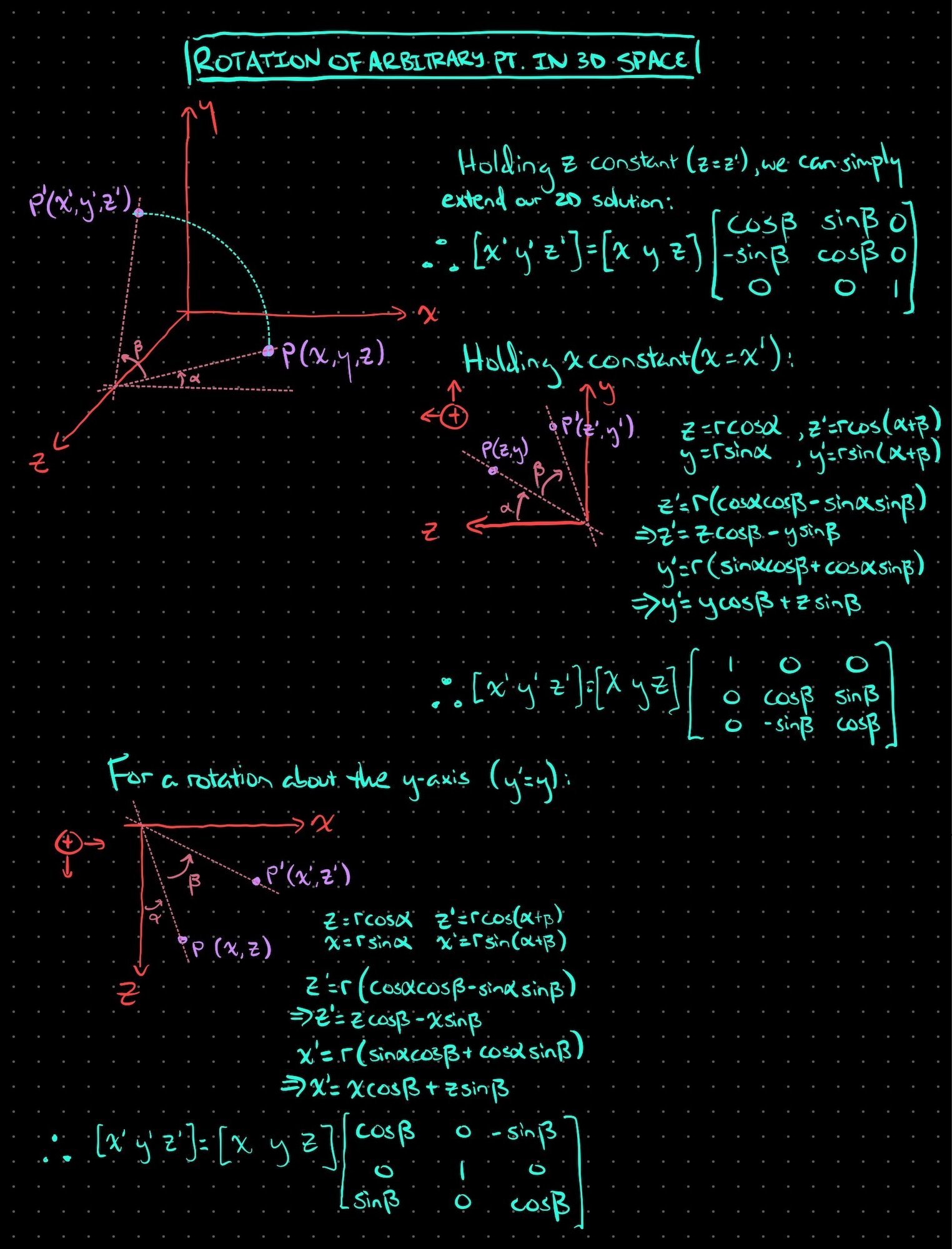
Figure 3: Derivation for z-axis, x-axis, and y-axis rotation matrices of an arbitrary point in 3D space.
Scales
Scaling any number up/down is inherently just a multiplication of that number, by the value one wishes to scale it. Hence, the scaling transformation in iOS is simply performed as follows:
                        _                 _
                       | s    0    0    0  |
                       |  x                |
                       |                   |
                       |  0   s    0    0  |
     [x   y   z   1] * |       y           |
                       |                   |
                       |  0   0    s    0  |
                       |            z      |
                       |                   |
                       |_0    0    0    1 _| // Apple's transformation matrix for scaling up/down by sx, sy, and sz.
Here, sx is the value by which one wishes to scale the x-coordinate, sy is the value by which one wishes to scale the y-coordinate, and sz is the value by which one wishes to scale the z-coordinate. Nothing fancy at all here.
Putting it all together
For any arbitrary transformation matrix as follows:
 _                          _
| m      m      m      m     |
|  1,1    1,2    1,3    1,4  |
|                            |
| m      m      m      m     |
|  2,1    2,2    2,3    2,4  |
|                            |
| m      m      m      m     |
|  3,1    3,2    3,3    3,4  |
|                            |
| m      m      m      m     |
|_ 4,1    4,2    4,3    4,4 _|
we now know that the rendering engine simply performs this calculation on every coordinate of the target view:
                    _                          _
                   | m      m      m      m     |
                   |  1,1    1,2    1,3    1,4  |
                   |                            |
                   | m      m      m      m     |
                   |  2,1    2,2    2,3    2,4  |
[x   y   z   1 ] * |                            |
                   | m      m      m      m     |
                   |  3,1    3,2    3,3    3,4  |
                   |                            |
                   | m      m      m      m     |
                   |_ 4,1    4,2    4,3    4,4 _|
The very last step that the engine performs is a normalization. Why? Well, while that extra dimension we added for translations is usually still going to be 1, it might not always be the case. So, say for example our new value ended up being [x' y' z' 10]. The last step would be to divide every value by 10, which naturally would give us: [x'/10 y'/10 z'/10 1 ]. At that point, the 1 is once again meaningless, and iOS simply drops it to obtain our new CGPoint of (x'/10, y'/10) and new zPosition of z'/10.
One could apply each transform individually, of course, but by multiplying varying combinations of rotations, scales, and translations together, one is able to create increasingly complex transformations to apply to a view in one go! This proves especially powerful when working with CAAnimation , as one may set the end value of a layer’s transform (or sublayerTransform, depending on the use case) to a compound transformation matrix in order to animate rotation, scale, and translation in one fell swoop.
If you’re interested in seeing how a CATransform goes from one value to another during an animation, you can actually check out the source code for the rendering engine here: libs-quartzcore/CAAnimation.m at master · gnustep/libs-quartzcore . There’s a method called “- (id) calculatedAnimationValueAtTime:onLayer:" that is essentially a giant if/else branch going through the various possible types of supported animation values, the last of which is CATransform3D.
One last thing…
UPDATE: I have since written up a proper dive into the derivation of why this single matrix entry is used to perform perspective transforms, so although the below text still applies, you can get a full run-down of the math behind it here.
Having reached this far, there may have been one concept that jumped out as not having been covered: how does iOS handle perspective changes? It turns out, there’s actually a specific value in the CATransform3D matrix that correlates directly to perspective: m₃₄. It’s tucked away in Apple’s archived documentation, under “Adding Perspective to Your Animations”, but it also has its roots in mathematics too. It’s a whole separate thing, but not to worry, that’s what Wikipedia’s for (I know, I know, I shouldn’t cite Wikipedia, but hey, this isn’t anything that’s going to run by the IEEE). That article describes a vector ex,y,z as the “display surface’s position relative to the camera”. For our purposes, the ‘display surface’ is analogous to a view, and the ‘camera’ can be thought of as the user’s eyes. Now, the transformation matrix that this article describes is:
 _                _
| 1   0   e  / e   |
|          x    z  |
|                  |
| 0   1   e  / e   |
|          y    z  |
|                  |
| 0   0    1 / e   |
|_              z _|
which, if we expand by the extra dimension and compare against our generic 4x4 transformation matrix, we find that 1/ez corresponds to that m₃₄. As it turns out, this particular matrix value is inversely proportional to the z-distance from the view’s surface to the ‘camera’. This means that larger values for that denominator (i.e. a smaller m₃₄ overall) result in flatter perspectives, whereas smaller values (i.e. a larger m₃₄ overall) correspond to more significant perspective shifts.
The API for a CATransform3D lets us modify m₃₄ directly, simply by:
transformation.m34 = 1 / 666 // here, 666 is the ez value
One can think of modifying this value as being equivalent to moving the vanishing point around when doing a perspective drawing.